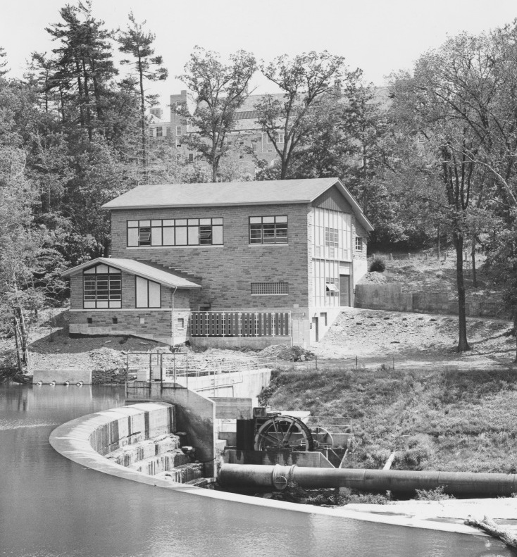
Chilled Water Plants
Cornell's centralized chilled water system, or district cooling system, uses an underground network of pipes to distribute cooling to campus buildings. Since its launch in the early 1960s, Cornell’s chilled water system has helped bridge and facilitate innovations, such as the 25 year success story, Lake Source Cooling (LSC). Thanks to LSC, which transfers cooling from the cold, deep water of Cayuga Lake, 98% of the cooling on Cornell’s Ithaca campus is renewable and refrigerant-free. During periods of peak demand and maintenance, LSC is supported by three chillers that use approved refrigerants.
Read on for more background on the evolution of the district cooling system and its chilled water plants…
The campus chilled water system is made up of three central plants with two large refrigeration machines and a chilled water thermal storage tank and a deep lake water-based non-contact cooling plant connected to a buried network of recirculated chilled water. The chilled water moves the heat entering the buildings to the central plants, which then reject the heat to the environment.
Chilled Water Plant I
The original plant, Chilled Water Plant 1 (CWP1), was built on the northern endowed campus and commissioned in 1963 with two 1,200-ton Carrier model 19C centrifugal chillers. The plant was expanded in 1965 to include another 1,200-ton Carrier model 19C centrifugal chiller for a total of 3,600 tons capacity (Chillers-1, 2, 3). Each chiller used R-11 as the refrigerant. Beebe Lake (Fall Creek) is a nearby natural water source that is used as a heat sink for the condenser water loop. Free cooling, via a plate and frame heat exchanger, was added in 1989 using the same natural heat sink. This allowed Cornell to meet all the winter cooling demands without mechanical refrigeration, using 38°F water cooled naturally by outdoor air from Beebe Lake. This plant was totally automated in 1989 when free cooling and variable speed pumping were added. The automation allowed the plant to cycle from one chiller to three without operator intervention.
Today, the original chillers have been decommissioned and removed, leaving only the winter lake-based free cooling is used as a backup to Lake Source Cooling. Also located in CWP1 is the Central Campus Energy Management and Control System (EMCS). This system provides alarming and monitoring of campus HVAC and electrical systems as well as central data collection of utility energy usage.
Chilled Water Plant II
Chilled Water Plant 2 (CWP2) was constructed in 1973-74 to meet the cooling loads on the statutory campus and included one 2,000-ton Carrier model 19CB centrifugal chiller (Chiller-5). Another 2,000-ton Carrier model 19CB centrifugal chiller (Chiller-6) was added in 1984. Both use R-114 refrigerant and evaporative cooling towers for heat rejection. The Statutory distribution system was interconnected with the Endowed system in 1984. CWP2 underwent an upgrade to include variable speed pumping and a current digital control system in 1992. This plant is now decommissioned and will be used in the future as loads grow.
Chilled Water Plant III
Chilled Water Plant 3 (CWP3) was constructed in 1974 on the southern portion of the endowed campus and included one 1,450-ton Carrier model 19FA centrifugal chiller using R-500 as the refrigerant (Chiller-4). A major expansion was completed in 1987 when a 4,000-ton Carrier model 17DA Centrifugal chiller, using R-12 refrigerant, was added (Chiller-7). An additional plate and frame heat exchanger was also added, as well as variable speed drives on the distribution pumping. This new chiller increased the system capacity by 44% and was the system's workhorse until Lake Source Cooling came online in 2001.
The unique feature of Chiller-7 was its variable speed compressor, which at the time, was the latest concept in large chiller efficiency. This was done using a 3,500 HP wound rotor motor and slip energy recovery AC drive and used 40% less energy annually than conventional chillers. The incremental cost of the drive was offset within two years by the increased energy savings that amounted to over 4-million kilowatt-hours per year. Chiller-7 was retrofitted to use R-134a as the refrigerant in 1998, and again in 2016 with a new starter.
A third plant expansion was completed in 1996 when a 2,000-ton Carrier model 17EX centrifugal chiller was installed using R-134a as the refrigerant (Chiller-8). This chiller was selected for 39° LCWT duty and tied directly into the TST system rather than the distribution system. Chiller-8 enhances the use of the TST through predominantly nighttime operation with off-peak electricity and cool condensing water temperatures. Chiller-8 included a beta version of Carrier's new "BAClink" gateway tied into CWP3. This was the first time, in a commercial setting, Carrier successfully utilized the new ASHRAE BACnet standard for interface to the chiller control. Another unique aspect of this project was the ability to use Chiller-7 for split duty, using part of its capacity to satisfy the system demand while using the remainder supplemented Chiller-8 for tank charging.
The Thermal Storage Tank was added in 1991.

